Category
- 4-20 /0-10 VDC ANALOG OUTPUT DEVICE
- Analog Card Mitsubishi
- Analog Card Omron
- Automation Service
- BREAKER
- DATA CABLE
- DATA CABLE
- DELTA HMI
- DELTA PLC
- Digital I/O Module
- HMI
- LOAD CELL
- MISUBISHI
- Mitsubishi FX
- MITSUBISHI HMI
- Omron
- Overload Relay
- PLC
- PLC UNLOCKER
- RS485 Modbus Temperature Controller
- Siemens HMI
- Techometer
- Temperature Controller
- USB TO RS485 Converter
- USB TO SERIAL DB9
- VFD
- YASKAWA
Our all Product is Original Brand, price should be negotiable.

Tag: Yokogawa
Showing all 2 results
-
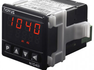
Indicator N1040i-RR, 240V
৳ 3,000Add to cartIndicatorInputThermo couple Type J,K,E,N,R,S,T,B; Pt100 in 3-wire technique; 0…20 mA; 4…20 mA; 0…50 mV; 0…5 V; 0…10 VInput impedancePt100, thermocouples and 0 … 50 mV:> 10 MΩ; 0 … 4 mV and 0 … 10 mV:> 500 kΩ, 0 … 20mA and 4 … 20mA; 100ΩConfigurationFront buttons / USBAccuracydepends on input, see data sheetA/D converter resolutionInternal: 15 bits, Display: 12000 levelsPower supply100…240 V AC (±10%), 50…60 HzDisplay2-row, 4-digit LED-Dispay, red and greenEnvironmental conditions0…50 °C, 80% RH at 30°C, at temperatures above 30 °C reduced by -3% RH per °CProtection categoryIP65 at front wall (by correct installation)Dimensions(LxWxH) 80 x 48 x 48 mmWeight0.1805 kg
-
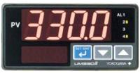
Yokogawa UM330 Digital Temperature Indicator
৳ 5,000Add to cart04-20ma Amp Output For PLC
PID ControllingThe Yokogawa UM330 digital indicator with alarms is a precision alarm instrument with universal input 1/8 DIN. For excellent monitoring operability, the UM330 displays process variables on a large display. The UM330 digital indicator is also provided with four alarm setting points (or setting outputs; one is optional). A retransmission output an 15 Vdc loop power supply are provided as standard. A communication function or 24Vdc loop power supply is available as an option to the UM330 digital indicator.
Signal Computation Function* Measure input computation: Bias addition (-100.0 to 100.0% of measured input range width), first-order lag filter (time constant off, 1 to 120 s)
* Contact input: Retains and displays maximum and minimum readings from measured variable. Resets the maximum and minimum readings.Alarm Function
Six different types of alarms are provided. If an alarm occurs, the alarm lamp indicates it. Four (one is optional) of the six can be used as relay contact outputs.
Alarm types:
* PV high limit, PV low limit, Deenergized on
* PV high limit, Deenergized on PV low limit
* Fault diagnosis, and FAIL outputSetting ranges for process variable alarms:
* PV alarms; -100.0 to 100.0% of measured input range
* Alarm hysteresis width; 0.0 to 100.0% of measured input range widthDelay timer:
* 0.00 to 99.59 (minute, second)
* An alarm is output when the delay timer expires after the alarm setpoint is reached
* Setting for each alarm is possible.Fault diagnosis alarm:
* Input burn out
* A/D conversion error
* TC RJC errorFAIL output: Software failure, Hardware failure
Stand-by action:
* Stand-by action can be set to make PV alarm
* OFF during start-upDisplay and Operation function
* PV display:4 digit display for engineering data
* Parameter display: 4-digit digital display for various data, including parameters
* Status display: 4 alarm LEDs (AL1, AL2, AL3, AL4)
* Operation keys: Up and Down keys, increase/decrease setpoints or various parameters
* SET/ENT key: Sets setpoint data, calls or switches various parameters
* SELECT display: Allows selection and registration of frequently changed parameters from the operation parameters during operation
* Security function: An operation inhibiting mode using a password is provided
Site Visitor (ভিজিটর)


 Users Today : 35
 Users Yesterday : 120
 This Month : 3172
 This Year : 35496
 Total Users : 68671
 Views Today : 51
 Total views : 667321
 Who's Online : 2

